Hauptmenü
Sie sind hier
Opto isolated CAT-Interface for Transceiver Yaesu FT817
1. Introduction
This article is about my home made CAT-Interface for connecting a PC or Notebook with a Radio Transceiver like the well known Yaesu FT-817 [4]. The interface transfers the audio signals from and to the transceiver as well as control lines like RxD and TxD. All lines are opto isolated. You can find a huge variety of those interfaces in the Web, but, as quite often, i wanted to design and build one on my own. The main feature here is that the audio signals are also optically isolated whereas many other interfaces use transformers for the same purpose.
The following picture shows the interface:

2. Schematic Diagram and Layout
The interesting part is - in fact - part I of the schematic diagram showing the opto isolated audio frequency path. The main component is the optocoupler HCNR200 [1] which consists of one LED and two photo diodes (PD). One PD is used for monitoring the signal and thus regulating the current of the LED in order to achieve high linearity between input signal and output signal.
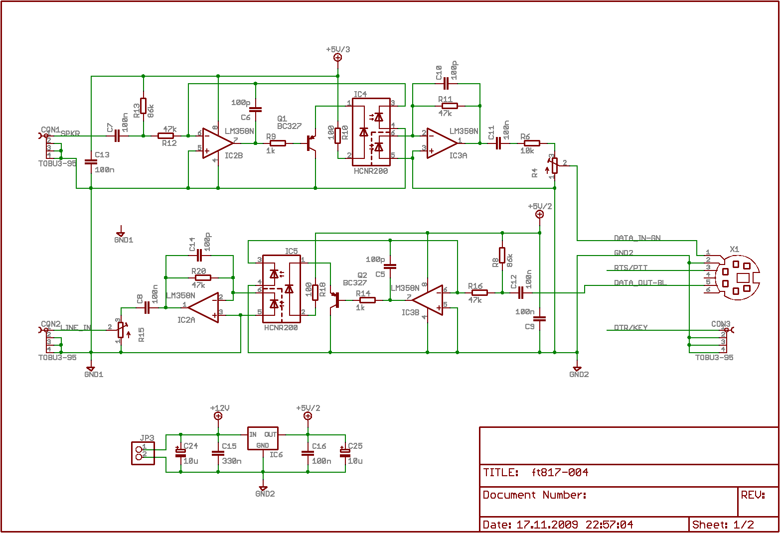
Basically, the shematic was taken from Ref [1], Figure 17 (Precision Analog Isolation Amplifier). The main difference is, that the CAT-interface operates in single supply mode in cotrast to the schematic in the data sheet which uses symmetric positive and negative supply voltages. There are two channels: the upper one for TX (soundcard to transceiver) and the lower one for the opposite direction (trasceiver to soundcard). No channel has any direct wire connection. The only connection is the capacitance of the optocouplers (being lass than 1 pF according to data sheet) and the copper lines on the PCB.
The second page of the schmatic diagram deals with the digital channels between Notebook/PC and transceiver. Many transceivers can be controlled remotely by using their built in serial interface. USB is so popular and therefore it does not make sense to support the classical serial interface connector with 9 pins (or even 25 pins). FTDI [2] offers a quite nice chip which makes a serial interface available for an USB device: FT232BM [3].

On the digital side, four channels are realized. One for TxD and RxD for exchanging data between Notebook/PC and Transceiver. In addition a third line can be used to control PTT (either RTS or DTR) and a fourth line for controlling a key in CW-mode (also either RTS or DTR). In the current configuration PTT is driven by RTS and consequently KEY is controlled by DTR.
Another advantage of USB is, that it also provides power. In this case, all components being connected to the Notebook or PC can be supplied with power from the USB-port. No additional power is needed. Unfortunately the same is not possible for the transceiver side. Even if the FT-817 has a 12 V pin on one of its connectors, it can not be used for powering the components on transceiver side of the interface. On the one hand, the pin is powered permanently (and not switched off if the transceiver is switched off) and on the other hand, there is a series resistor in the ft817, which makes it impossible to drive the LEDs of the opto couplers. Voltage breaks down completely, if the interface is connected. The easiest way for powering the transceiver side of the CAT-interface to me was simply to use rechargeable batteries. I have chosen an accu block consisting of 7 NiMH-cells each having a capacity of ca. 700 mAh. The total voltage is well above 8V, which is sufficient for the voltage regulator IC6 (see part I), which is not a low drop type.
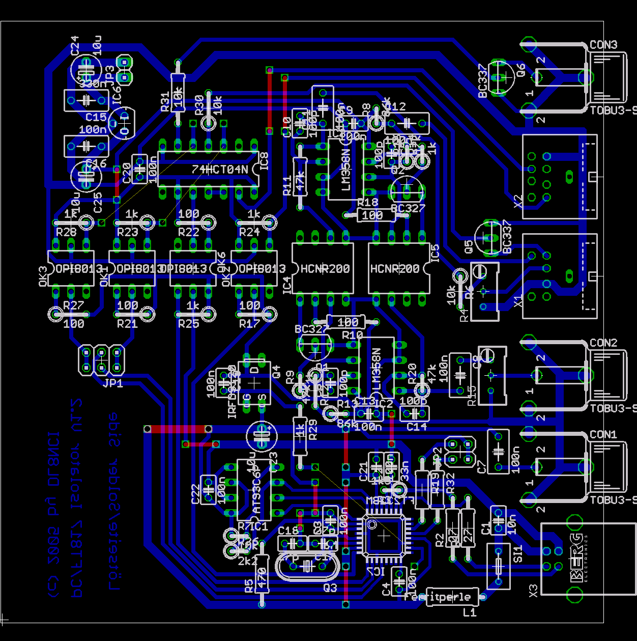
The layout of the PCB is shown in the next picture. Basically it is a single side layout. Few connections have to be made on the component side with some pieces of wire. The shorter ones are depicted as lines on the component side, the longer ones are unconnected wires in color yellow. In addition, some minor changes were applied which cause some differences in comparison with the photos.