Main menu
You are here
A Simple Single Ended PCL86 Stereo Audio Amplifier
1. Introduction
This page is about a new project with tubes. A friend of mine recently started building a vintage equalizer like it was used in radio stations and record studios in the fifites and sixties. I am helping him a little bit with purchasing all the electronics parts he needs. Once we have results i probably will present them here. But for now i want to present some photos of a prototype amplifier with the tube PCL86 in single ended configuration. This tube consists of a triode and a pentode which are used as audio preamplifier and audio power amplifier respectively. Well ... power in this case means roughly 4 Watts.
2. The Prototype
The design is completely based on the project from Hans Borngräber (http://www.roehrenkramladen.de/PCL86/pcl86_1.htm). If you search for PCL86 amplifiers you will usually find out that they are quite similar. Maybe with the only exception where the amplifier runs with low voltage, which requires different components.
I will develop this page in the next days and weeks; but for the time beeing i simply show some pictures of the prototype.
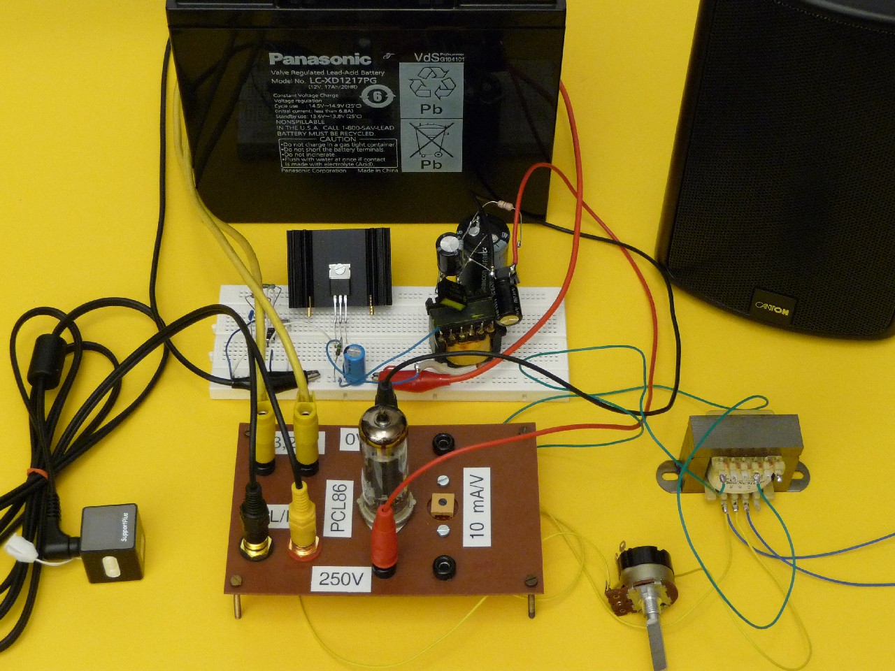
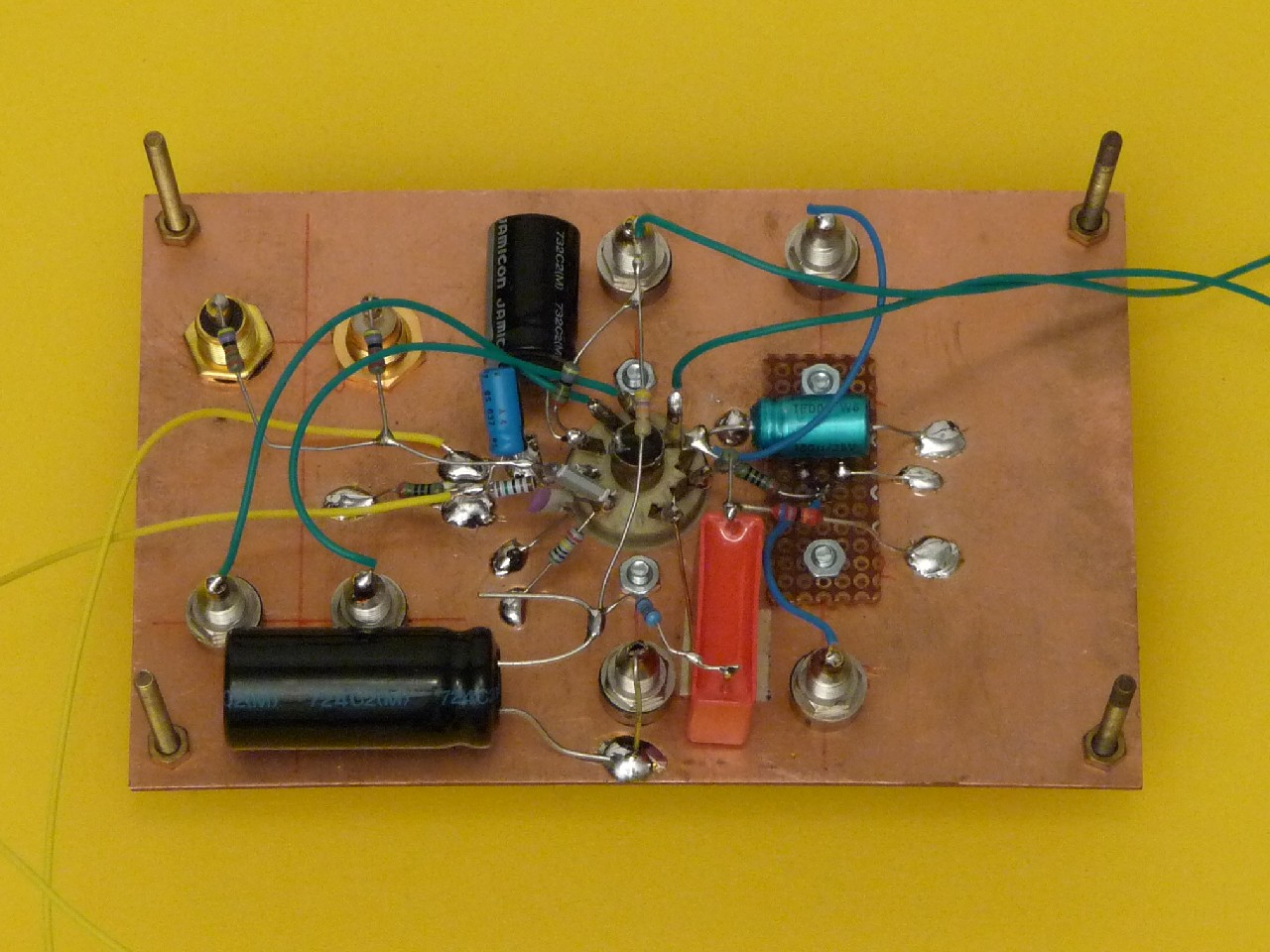
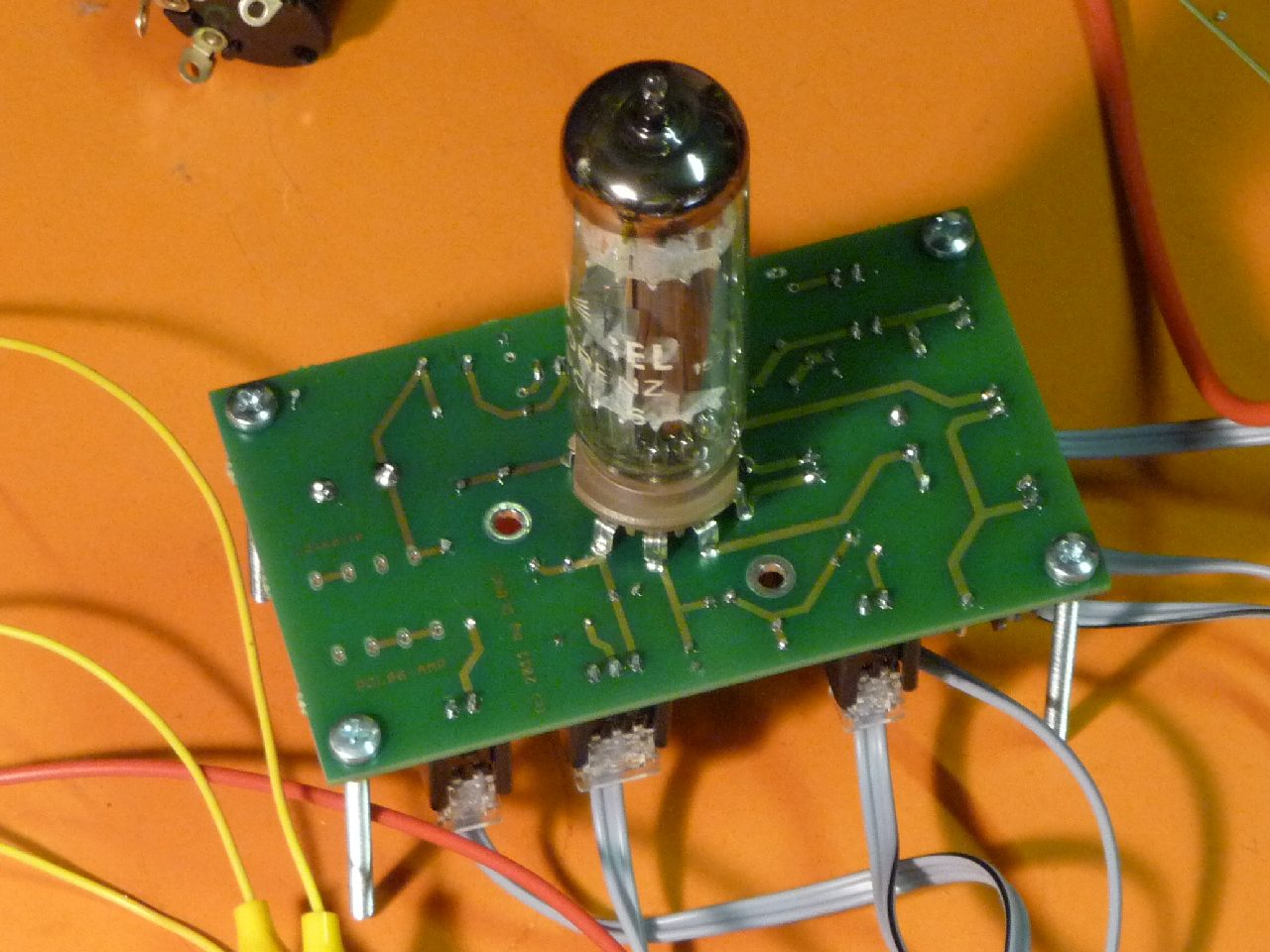
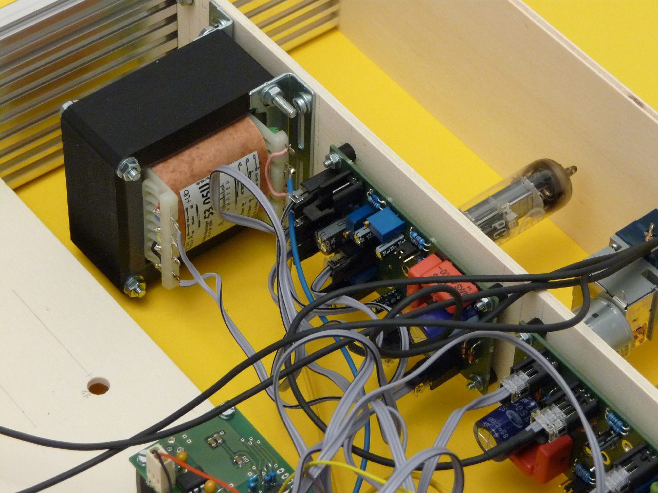
This picture shows the whole setup. In the middle you can see the amplifier with the tube PCL86 in the middle and some connectors arranged around the tube. Next to the tube is the trim poti for setting the grid bias voltage. The green wires are connected to the output transformer which is in this case a 100 V transformer. Not a perfect solution but it sounds not too bad! The 8 Ohm winding then is connected to the speaker (blue wires) in the right upper corner on the image. At the top edge of the image there is a 12 V rechargable battery being the power supply of the experiment. The heater of the tube is connected directly (thick yellow wires) with the battery. On the white board i have set up a flyback converter consisting of an NE555, IRF510, an old transformer of a PC-power supply, a diode and some capacitors on the secondary winding of the transformer. The converter produces 250 V which is ideal for supplying the amplifier. So .. if you like tube sound and you have only 12 V available ... here we are ... On the left side you see the MP3 player which is connected to the amplifier. Ah ... and the poti near the output transformer is for controlling feedback of the whole amplifier.
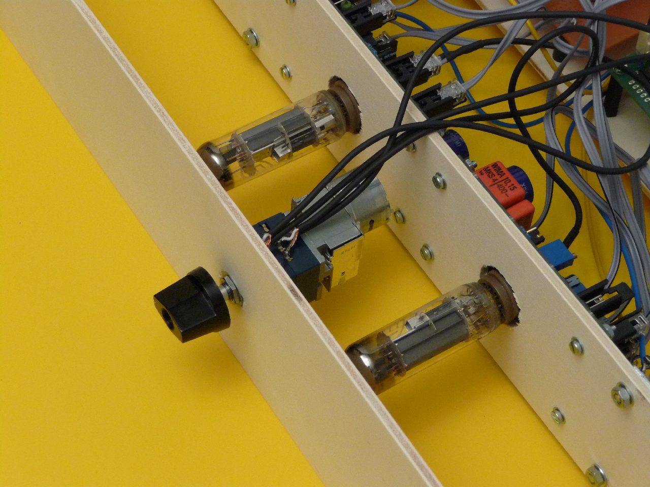
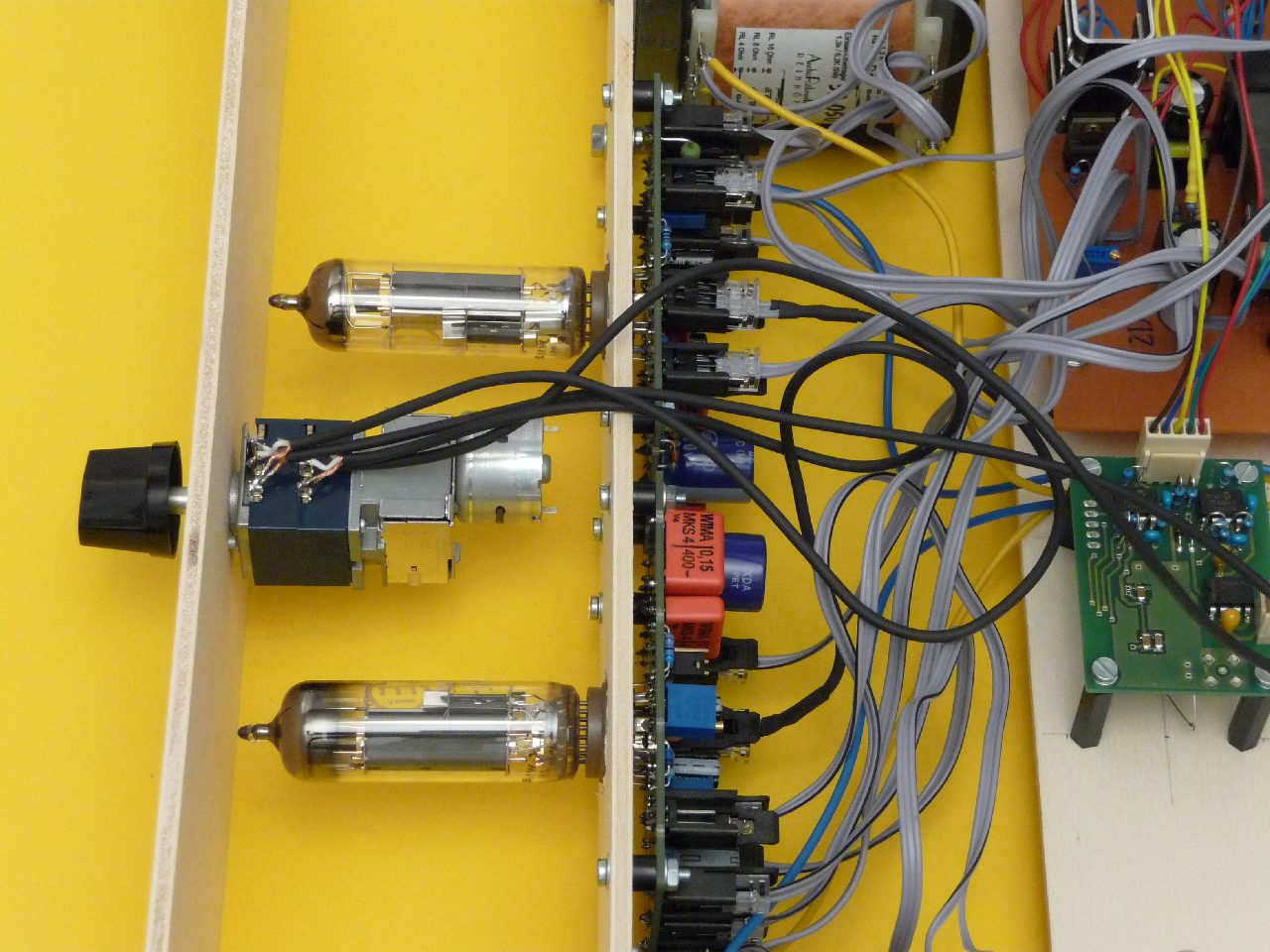
Other perspectives of the whole arrangement ...

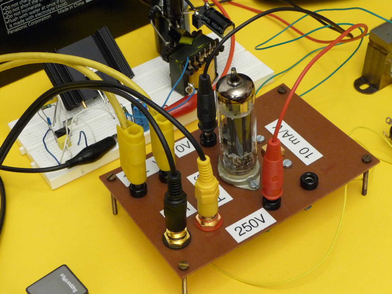
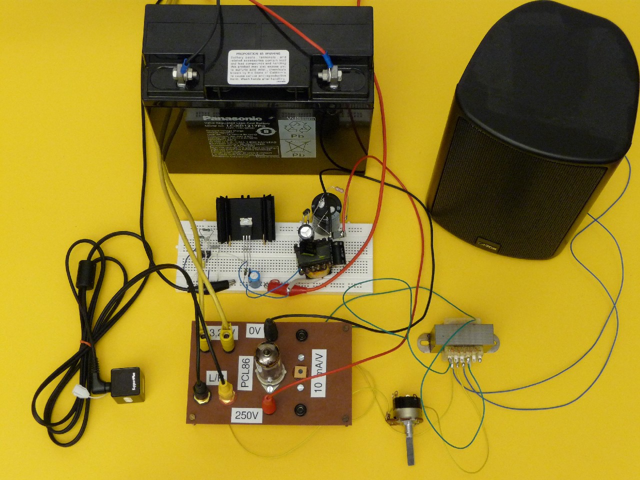
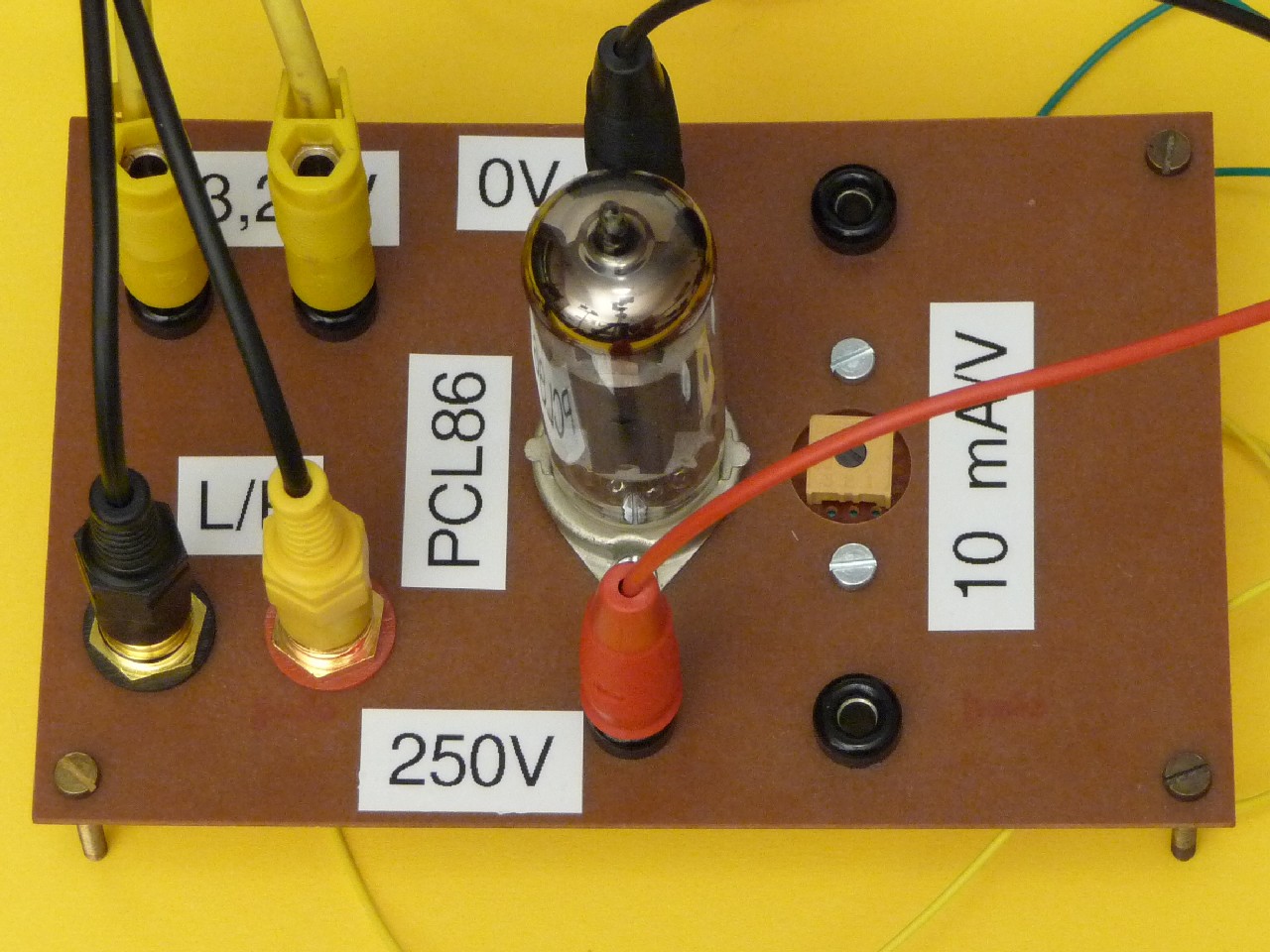
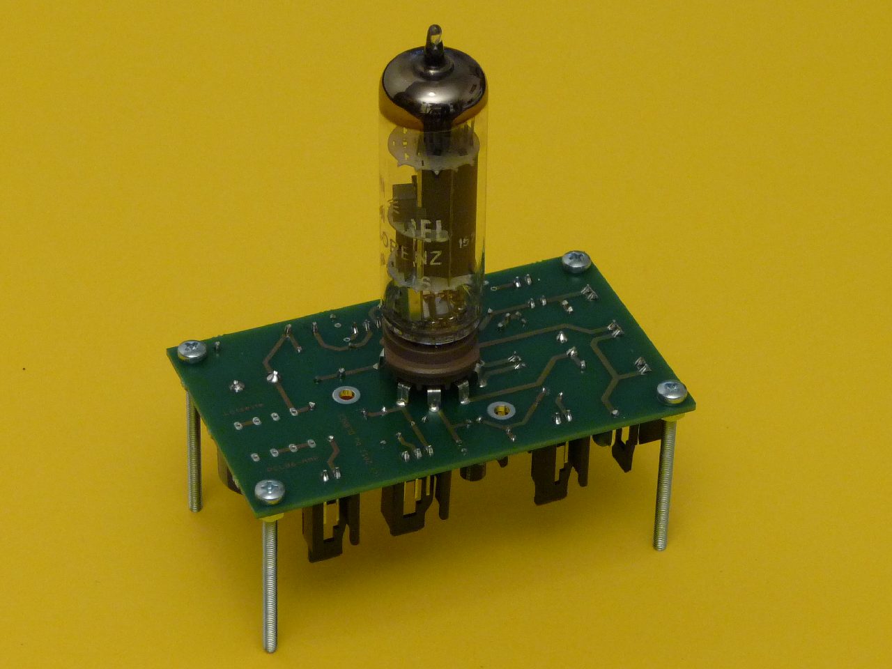
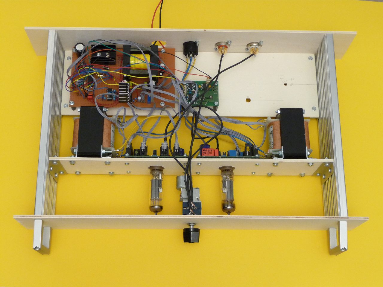
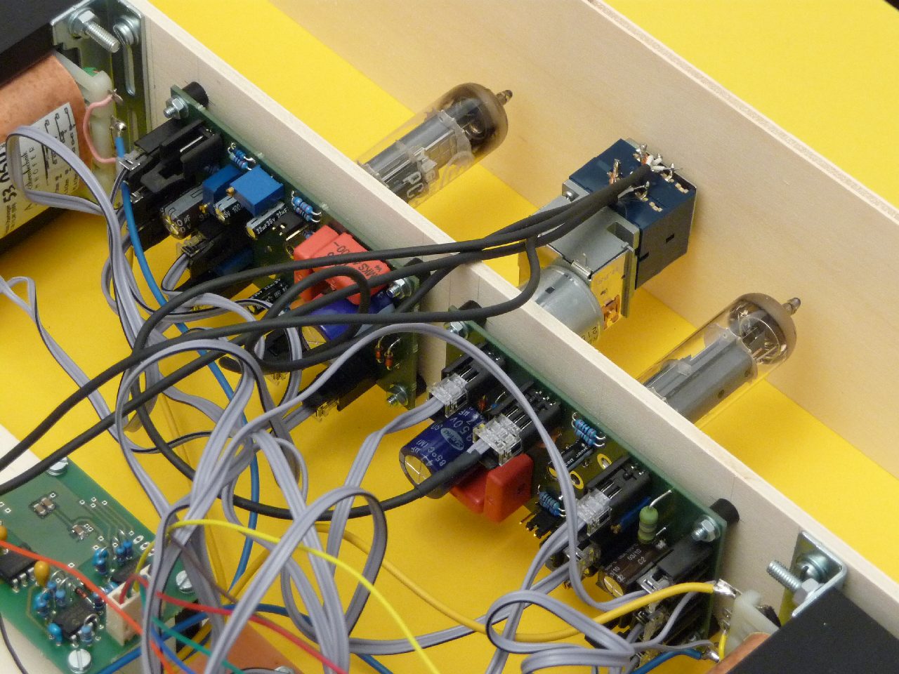
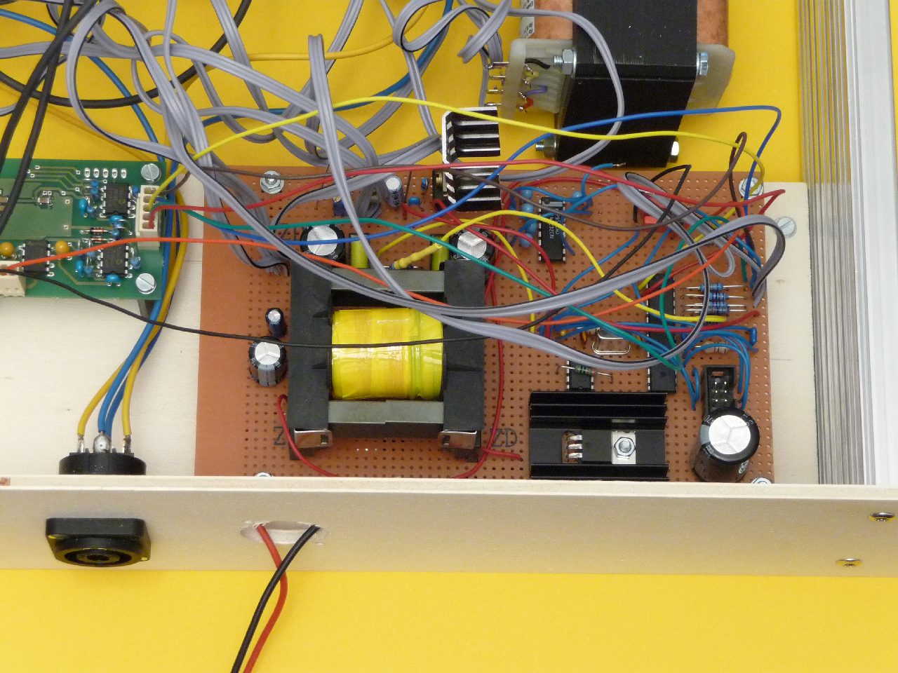
A detailed picture of the prototype from top side and a bottom view showing all the components and the wiring
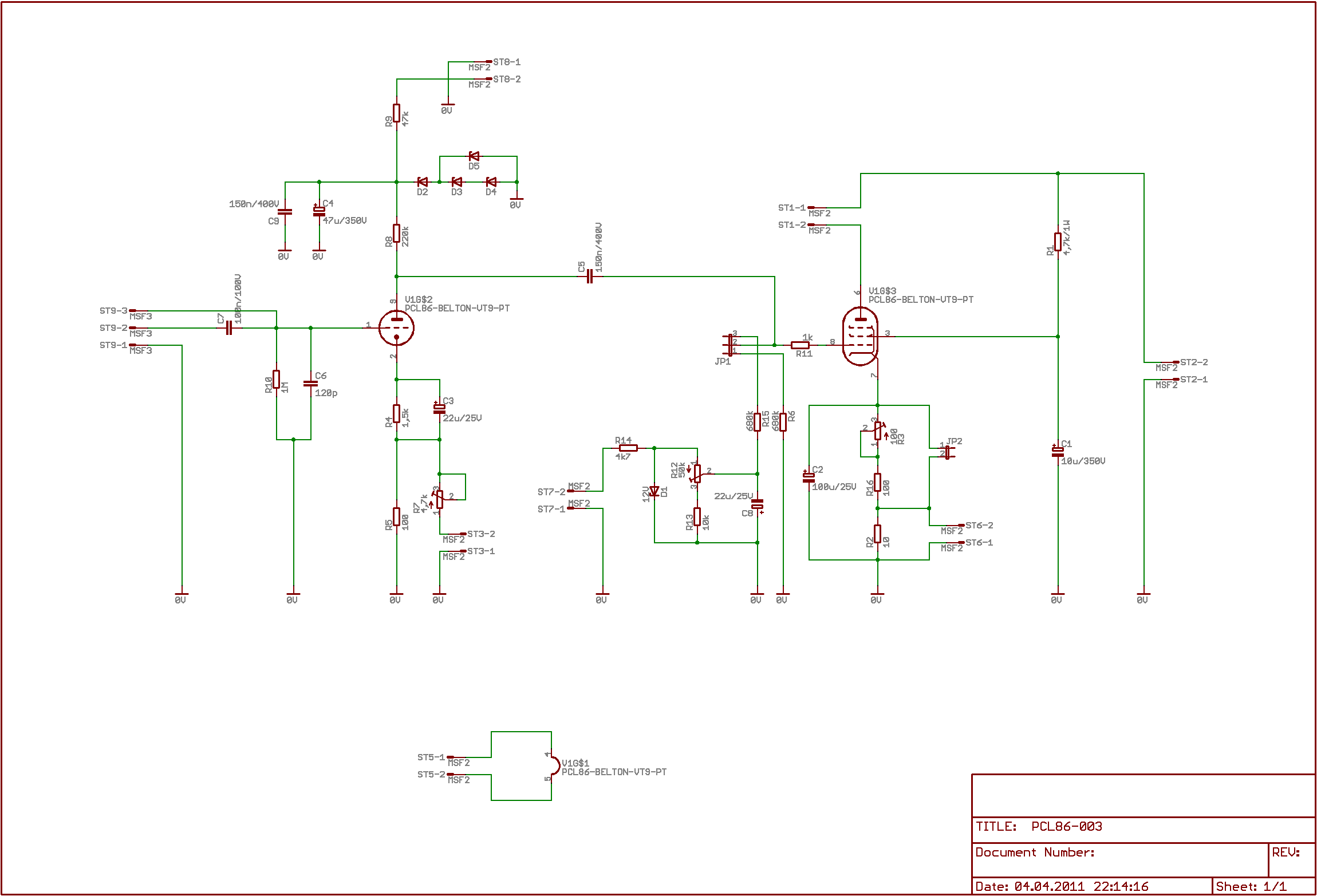
And finally the preliminary schematic which is completely gased on http://www.roehrenkramladen.de/PCL86/pcl86_1.htm.

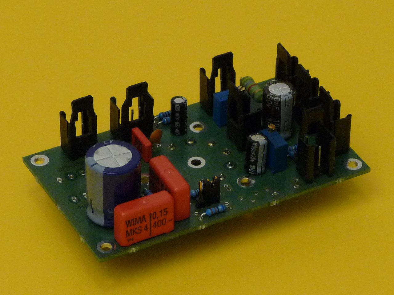
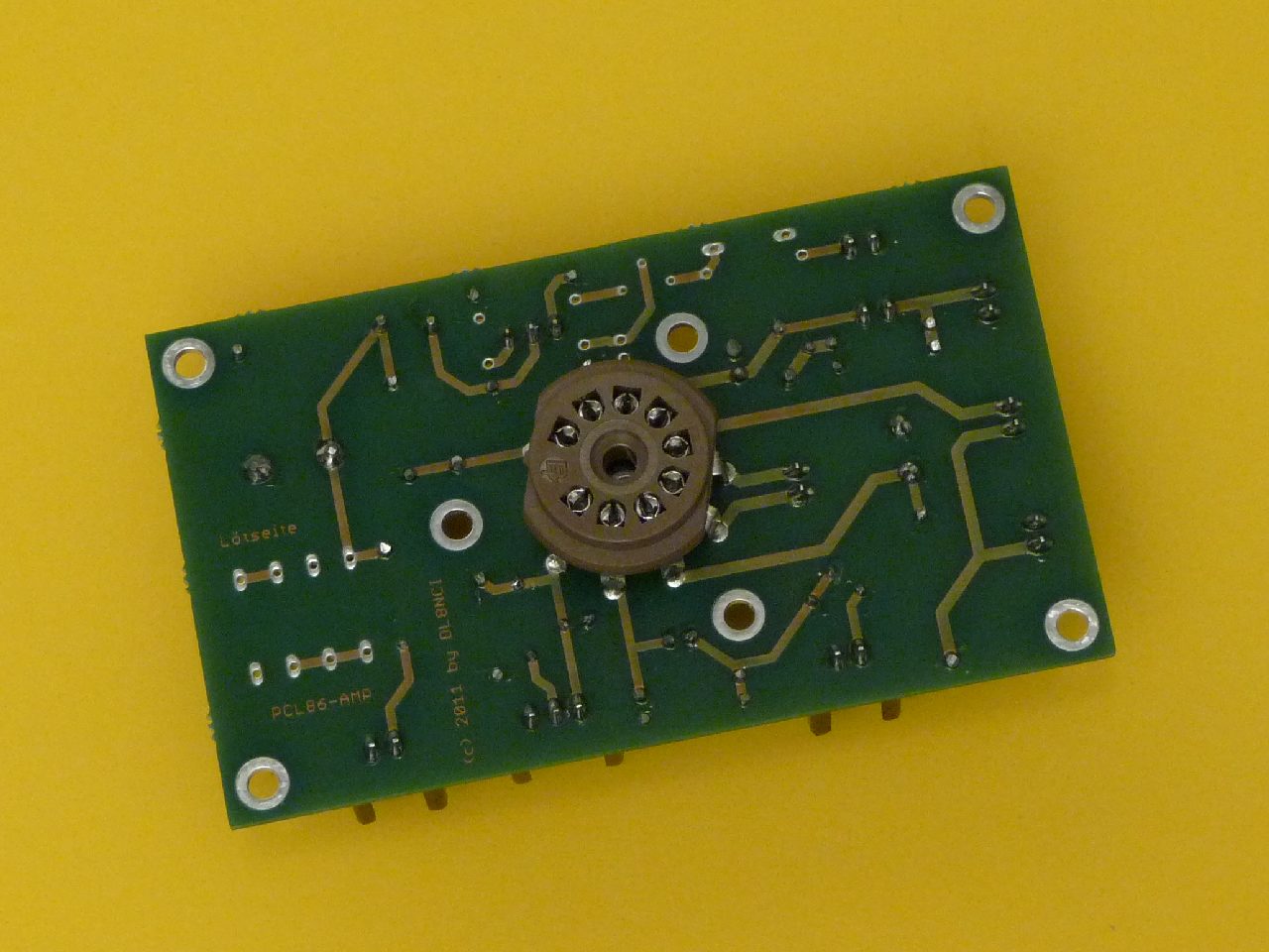
3. The almost final Design
Since the prototype worked so well i decided to rework the schematic a little bit and to design a layout for a PCB. The following pictues show the results of the redesign. It is worth mentioning that the tube is mounted from the solder side. This makes it possible that the tube can be easily placed on the top cover of the cabinet without losing space for the other components. But even if you want to hide the tubes inside the cabinet, it makes sense to separate the heat producing tube as far as possible from the other components of the board.

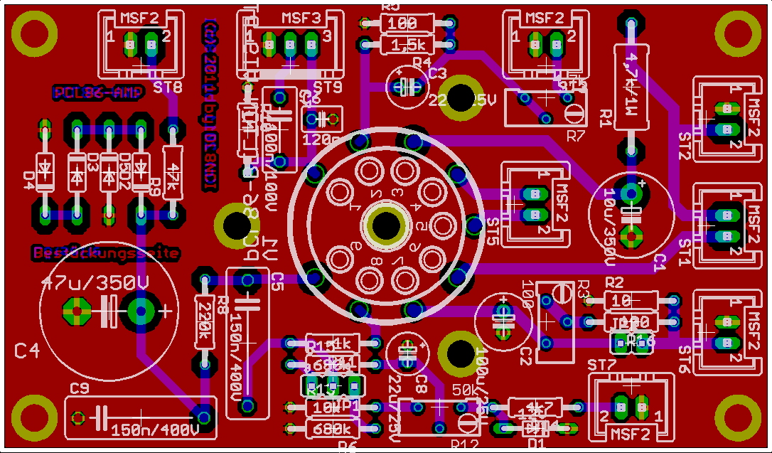
The next two pictures show the schematic and the layout of the small PCB (54 x 92 mm). The design is pretty much like many others. One highlight might be the alternative way for generating grid bias voltage. If you connect pins 1 and 2 of Jumper JP1 you have the classical grid bias generation by utilizing the voltage across the cathode resistors. Alternatively you can supply a negative voltage und use it for grid bias. In that case, connect pins2 and 3 of jumper JP1 and, in addition, set a jumper on JP2 and shorten most of the cathode resistors. However, i did not yet test the option with external negative voltage supply. Therefore consider the component values for the relevant portion of the schematic as preliminary.
In addition, the supply voltage for the triode system can be stabilized by use of two (D2 and D5) or three (D2, D3, D4) Z-diodes. Again, i did not yet test this option. Typical voltage is around 200 V; so use either two 100 V Z-Diodes or three 68 V Z-Diodes.
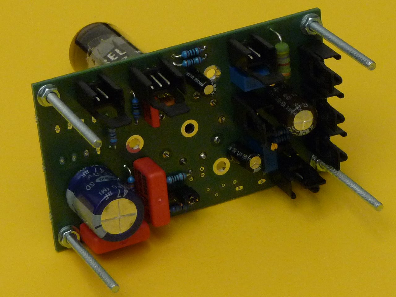
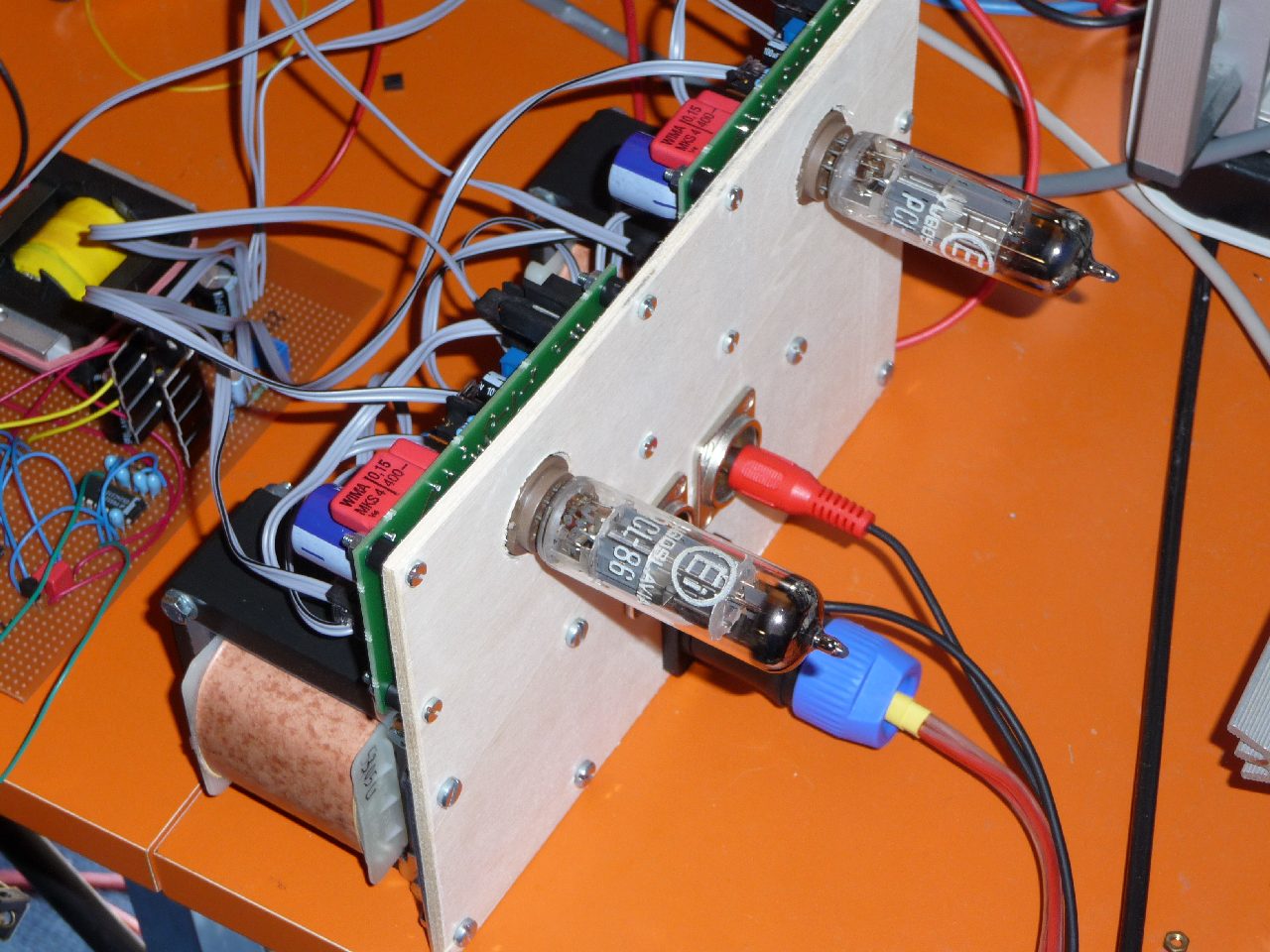
The next two pictures show the amplifier in the lab ...
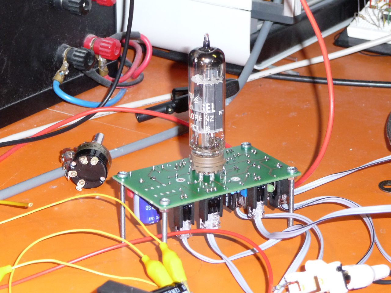
Next step - i just received the output transformers. In order to have all components in a fixed and stable position, i mounted the amplifier boards and the transformers simply on a wooden board. This arrangement looks quite unusual but it is more secure than having no mounting board at all and it is more flexible than using a metal chassis. I have connected the output of the transformers to two small boxes which are not shown on the pictures below. My first audio impression is quite promising. What i want to do next is finding a resonable case - i think a 19 inch rack mount should be ok. I will hide almost everything in the housing because i personnally do not like to have the tubes and the transformers outside the case - in contrast to many others. Another topic is adjusting the (negative) feedback.


On the breadboard in front of the amplifier you can see the experimental version of a switching mode power supply of flyback type which generates plate and filament voltage out of a single source of only 12 V and drawing 3 A current. Plate voltage (ca. 200 V) is controlled and regulated by the SMPS whereas filament volage (ca. 13 V) is additionally regulated by a Low-Drop linear regulator. More details will follow at a later point in time. In addition, i will design a PCB for this SMPS.
3. Final Design - again as Prototype

to be continued ...